The Arduino Compatible for STM32G474 Nucleo development board
English | 中文
1 RTduino - Arduino Ecosystem Compatibility Layer for RT-Thread
The STM32G474 Nucleo development board has been fully adapted with the RTduino software package, which is an Arduino Ecosystem compatibility layer for RT-Thread. Users can program this BSP according to Arduino programming conventions and use a large number of libraries available in the Arduino community, providing a significant enhancement to the RT-Thread ecosystem. For more information, please refer to the RTduino software package documentation.
1.1 How to Enable Arduino Ecosystem Compatibility Layer for this BSP
Enter the menuconfig command under Env tool or select RT-Thread Settings under RT-Thread Studio IDE:
Hardware Drivers Config --->
    Onboard Peripheral Drivers --->
        [*] Compatible with Arduino Ecosystem (RTduino)
2 Arduino Pinout
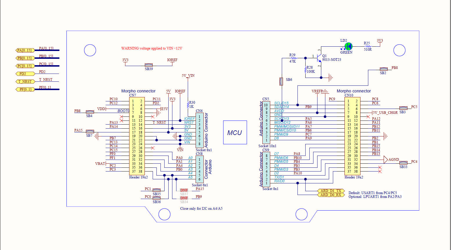
For additional information on pin layout, refer to pins_arduino.c and pins_arduino.h.
| Arduino Pin Number | STM32 Pin Number | 5V Tolerance | Remarks |
|---|---|---|---|
| 0 (D0) | PC5 | Yes | |
| 1 (D1) | PC4 | Yes | |
| 2 (D2) | PA10 | Yes | Serial2-RX, default controlled by RT-Thread's UART device framework uart1 |
| 3 (D3) | PB3 | Yes | PWM2-CH2, default controlled by RT-Thread's PWM device framework pwm2 |
| 4 (D4) | PB5 | Yes | |
| 5 (D5) | PB4 | Yes | PWM3-CH1, default controlled by RT-Thread's PWM device framework pwm3 |
| 6 (D6) | PB10 | Yes | PWM2-CH3, default controlled by RT-Thread's PWM device framework pwm2 |
| 7 (D7) | PA8 | Yes | |
| 8 (D8) | PA9 | Yes | Serial2-TX, default controlled by RT-Thread's UART device framework uart1 |
| 9 (D9) | PC7 | Yes | PWM8-CH2, default controlled by RT-Thread's PWM device framework pwm8 |
| 10 (D10) | PB6 | Yes | PWM4-CH1, default controlled by RT-Thread's PWM device framework pwm4 |
| 11 (D11) | PA7 | Yes | PWM3-CH2, default controlled by RT-Thread's PWM device framework pwm3 |
| 12 (D12) | PA6 | Yes | |
| 13 (D13) | PA5 | Yes | Onboard User LED |
| 14 (D14) | PB9 | Yes | I2C1-SDA, default controlled by RT-Thread's I2C device framework i2c1 |
| 15 (D15) | PB8 | Yes | I2C1-SCL, default controlled by RT-Thread's I2C device framework i2c1 |
| 16 (D16) | PC13 | Yes | |
| 17 (A0) | PA0 | Yes | ADC1-CH1, default controlled by RT-Thread's ADC device framework adc1 |
| 18 (A1) | PA1 | Yes | ADC1-CH2, default controlled by RT-Thread's ADC device framework adc1 |
| 19 (A2) | PA4 | Yes | ADC2-CH17, default controlled by RT-Thread's ADC device framework adc2 |
| 20 (A3) | PB0 | Yes | ADC1-CH15, default controlled by RT-Thread's ADC device framework adc1 |
| 21 (A4) | PC1 | Yes | ADC1-CH7, default controlled by RT-Thread's ADC device framework adc1 |
| 22 (A5) | PC0 | Yes | ADC1-CH6, default controlled by RT-Thread's ADC device framework adc1 |
| 23 (A6) | -- | On-chip reference voltage ADC, default controlled by RT-Thread's ADC device framework adc1 | |
| 24 (A7) | -- | On-chip temperature sensor ADC, default controlled by RT-Thread's ADC device framework adc1 |
Notice:
- Don't use a same hardware timer to drive PWM (analogRead) and servos at same time, because hardware timers can only generate a same frequency for 4 PWM channels. Otherwise, it could cause a failure when drive servos.
References:


