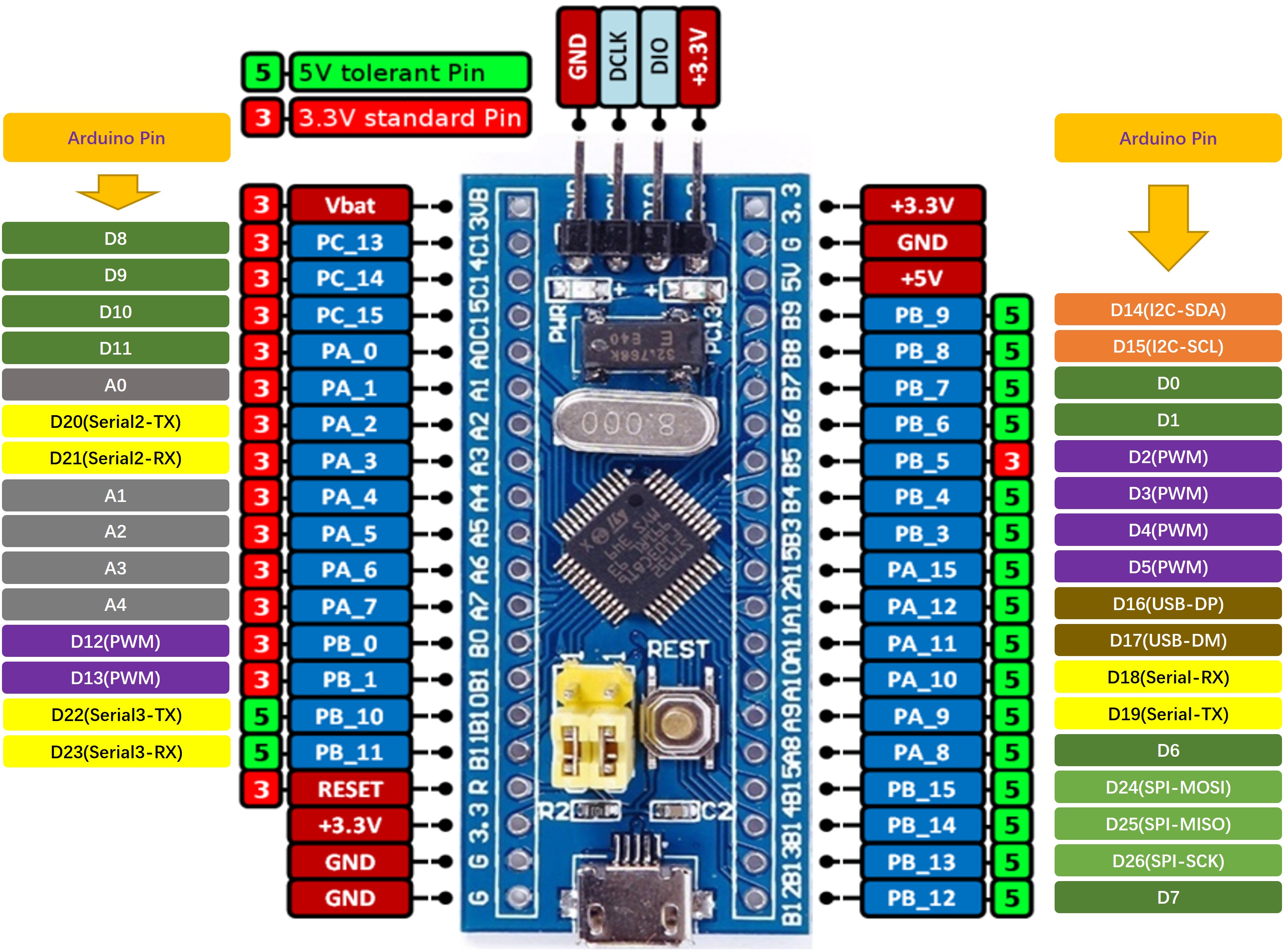
The Arduino Compatible of STM32 Blue Pill Board
English | 中文
1 RTduino - Arduino Ecosystem Compatibility Layer for RT-Thread
STM32 Blue Pill board has support RTduino. Users can use Arduino APIs, third party libraries and programming method to program on Blue Pill board.
1.1 How to Enable RTduino
Please go to the RTduino repository to see the details.
Hardware Drivers Config --->
    Onboard Peripheral Drivers --->
        [*] Support Arduino
2 Arduino Pinout
| Arduino Pin | STM32 Pin | 5V Tolerate | 备注 |
|---|---|---|---|
| 0 (D0) | PB7 | Yes | |
| 1 (D1) | PB6 | Yes | |
| 2 (D2) | PB5 | No | PWM3-CH2. Token over by RT-Thread PWM device by default |
| 3 (D3) | PB4 | Yes | PWM3-CH1. Token over by RT-Thread PWM device by default |
| 4 (D4) | PB3 | Yes | PWM2-CH2. Token over by RT-Thread PWM device by default |
| 5 (D5) | PA15 | Yes | PWM2-CH1. Token over by RT-Thread PWM device by default |
| 6 (D6) | PA8 | Yes | |
| 7 (D7, SS) | PB12 | Yes | SPI chip select by default |
| 8 (D8, LED_BUILTIN) | PC13 | No | Build-in LED |
| 9 (D9) | PC14 | No | |
| 10 (D10) | PC15 | No | |
| 11 (D11) | PA0 | No | |
| 12 (D12) | PB0 | No | PWM3-CH3. Token over by RT-Thread PWM device by default |
| 13 (D13) | PB1 | No | PWM3-CH4. Token over by RT-Thread PWM device by default |
| 14 (D14) | PB9 | Yes | I2C-SDA. Token over by RT-Thread I2C device by default |
| 15 (D15) | PB8 | Yes | I2C-SCL. Token over by RT-Thread I2C device by default |
| 16 (D16) | PA12 | Yes | USB-DP. Token over by TinyUSB software package by default. |
| 17 (D17) | PA11 | Yes | USB-DM. Token over by TinyUSB software package by default. |
| 18 (D18) | PA10 | Yes | Serial-Rx. Token over by RT-Thread UART device by default |
| 19 (D19) | PA9 | Yes | Serial-Tx. Token over by RT-Thread UART device by default |
| 20 (D20) | PA2 | No | Serial2-Tx. Token over by RT-Thread UART device by default |
| 21 (D21) | PA3 | No | Serial2-Rx. Token over by RT-Thread UART device by default |
| 22 (D22) | PB10 | Yes | Serial3-Tx. Token over by RT-Thread UART device by default |
| 23 (D23) | PB11 | Yes | Serial3-Rx. Token over by RT-Thread UART device by default |
| 24 (D24) | PB15 | Yes | SPI-MOSI. Token over by RT-Thread SPI device by default |
| 25 (D25) | PB14 | Yes | SPI-MISO. Token over by RT-Thread SPI device by default |
| 26 (D26) | PB13 | Yes | SPI-SCK. Token over by RT-Thread SPI device by default |
| 27 (A0) | PA1 | No | ADC1-CH1. Token over by RT-Thread ADC device by default |
| 28 (A1) | PA4 | No | ADC1-CH4. Token over by RT-Thread ADC device by default |
| 29 (A2) | PA5 | No | ADC1-CH5. Token over by RT-Thread ADC device by default |
| 30 (A3) | PA6 | No | ADC1-CH6. Token over by RT-Thread ADC device by default |
| 31 (A4) | PA7 | No | ADC1-CH7. Token over by RT-Thread ADC device by default |
| 32 (A5) | -- | ADC of chip internal reference voltage. Token over by RT-Thread ADC device by default | |
| 33 (A6) | -- | ADC of chip internal temperature. Token over by RT-Thread ADC device by default |
Note:
- If you drive the servo and call the analogWrite function at the same time, you need to select the PWM signal pins generated by different timers. Since the 4 channels of the STM32 timer need to maintain the same frequency, if the PWM generated by the same timer is used to drive the servo and analogWrite respectively , it may cause the servo to fail.
- More information about Arduino pinout, please see pins_arduino.c and pins_arduino.h
3 Communication
3.1 I2C Bus
I2C bus is D14 and D15 pins. Users can directly include the #include <Wire.h>, which is the Arduino official I2C header file, to use the I2C bus.
3.2 SPI Bus
SPI bus is D24, D25 and D26 pins. Users can directly include the #include <SPI.h>, which is the Arduino official SPI header file, to use the SPI bus. In addition, chip select pin (SS) also is used, which is D7 by default.
3.3 USB
This board supports USB virtual COM by default. See example.
3.4 Serial
This board supports to use Serail. method to use uart1 device; use Serial2. method to use uart2 device; use Serial3. method to use uart3 device. See example.
