|
|
||
|---|---|---|
| .. | ||
| applications | ||
| board | ||
| bsp | ||
| .config | ||
| .ignore_format.yml | ||
| Kconfig | ||
| README.md | ||
| README_zh.md | ||
| SConscript | ||
| SConstruct | ||
| rtconfig.h | ||
| rtconfig.py | ||
README.md
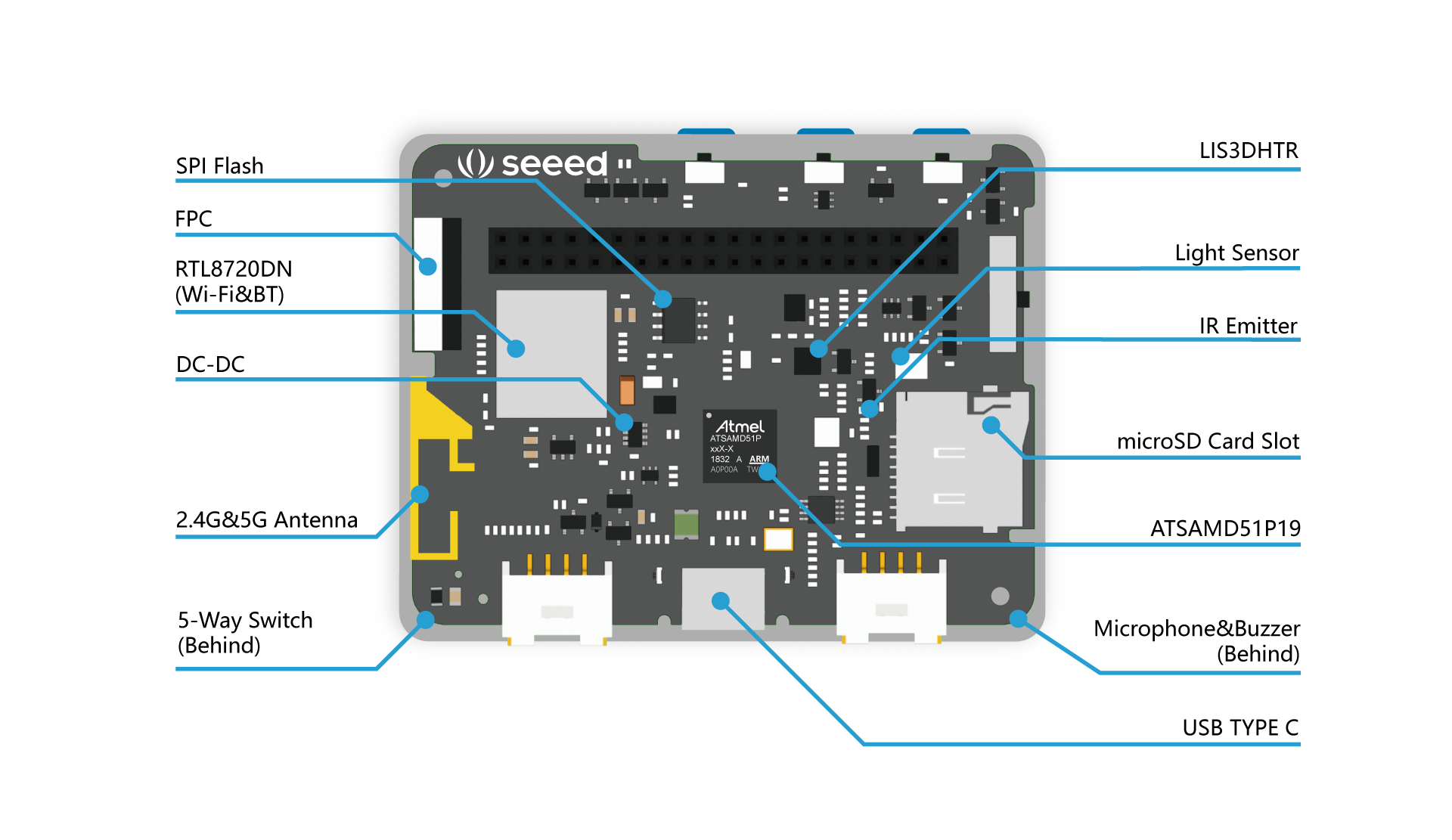
Seeed Wio-Terminal BSP Introduction
- MCU: ATSAMD51P19A @120MHz, 512KB FLASH, 192KB RAM
- D51: Cortex-M4F + Adavanced Feature Set
- Pin: G=48 pins, J=64 pins, N=100 pins, P=128 pins
- Flash: 18=256KB, 19=512KB, 20=1024KB (size=2^n)
- SRAM : 128KB(Flash 256KB), 192KB(Flash 512KB), 256KB(Flash 1MB)
- Datasheet: https://www.microchip.com/en-us/product/ATSAMD51P19
KEY FEATURES
Core
- 32-bit Arm® Cortex®-M4 core with single-precision FPU and 4 KB combined instruction cache and data cache; frequency up to 120 MHz, MPU, 403 CoreMark® at 120 MHz, and DSP instructions
Memories
-
1 MB/512 KB/256 KB in-system self-programmable Flash with:
- Error Correction Code (ECC)
- Dual bank with Read-While-Write (RWW) support
-
EEPROM hardware emulation
-
128 KB, 192 KB, 256 KB SRAM main memory
-
64 KB, 96 KB, 128 KB of Error Correction Code (ECC) RAM option
-
Up to 4 KB of Tightly Coupled Memory (TCM)
-
Up to 8 KB additional SRAM
-
Can be retained in backup mode
-
Eight 32-bit backup registers
System
- Power-on Reset (POR) and Brown-out detection (BOD)
- Internal and external clock options
- External Interrupt Controller (EIC)
- 16 external interrupts
- One non-maskable interrupt
- Two-pin Serial Wire Debug (SWD) programming, test, and debugging interface
High-Performance Peripherals
- 32-channel Direct Memory Access Controller (DMAC)
- Up to two SD/MMC Host Controller (SDHC)
- Up to 50 MHz operation
- 4-bit or 1-bit interface
- Compatibility with SD and SDHC memory card specification version 3.01
- Compatibility with SDIO specification version 3.0
- Compliant with JDEC specification, MMC memory cards V4.51
- One Quad I/O Serial Peripheral Interface (QSPI)
- Dedicated AHB memory zone
- One Ethernet MAC (SAM E53 and SAM E54)– 10/100 Mbps in MII and RMII with dedicated DMA
- IEEE® 1588 Precision Time Protocol (PTP) support
- IEEE 1588 Time Stamping Unit (TSU) support
- IEEE802.3AZ energy efficiency support
- Support for 802.1AS and 1588 precision clock synchronization protocol
- Wake on LAN support
- Up to two Controller Area Network (CAN) (that is., SAM E51 and SAM E54)
- Support for CAN 2.0A/CAN 2.0B and CAN-FD (ISO 11898-1:2016)
- One Full-Speed (12 Mbps) Universal Serial Bus (USB) 2.0 interface
- Embedded host and device function
- Eight endpoints
- On-chip transceiver with integrated serial resistor
System Peripherals
- Up to 114 I/O lines with external interrupt capability (edge- or level-sensitivity), debouncing, glitch filtering and On-die Series Resistor Termination
- Five Parallel Input/Output Controllers (PIO)
- 32-channel Event System
- Up to eight Serial Communication Interfaces (SERCOM), can be configured as USART/I2C/SPI
- Up to eight 16-bit Timers/Counters (TC), can be configured as 8/16/32bit TC.
- Two 24-bit Timer/Counters for Control (TCC), with extended functions
- Up to Three 16-bit Timer/Counters for Control (TCC) with extended functions.
- 32-bit Real Time Counter (RTC) with clock/calendar function
- Up to 4 wake-up pins with tamper detection and debouncing filter
- Watchdog Timer (WDT) with Window mode
- CRC-32 generator
- One two-channel Inter-IC Sound Interface (I2S)
- Position Decoder (PDEC)
- Frequency meter (FREQM)
- Four Configurable Custom Logic (CCL)
- Dual 12-bit, 1 MSPS Analog-to-Digital Converter (ADC) with up to 16 channels each:
- Dual 12-bit, 1 MSPS output Digital-to-Analog Converter (DAC)
- Two Analog Comparators (AC) with Window Compare function
- One temperature sensor
- Parallel Capture Controller (PCC)
- Peripheral Touch Controller (PTC) - Capacitive Touch buttons, sliders, and wheels
Cryptography
- One Advanced Encryption System (AES) with 256-bit key length and up to 2 MB/s data rate
- Five confidential modes of operation (ECB, CBC, CFB, OFB, CTR)
- Supports counter with CBC-MAC mode
- Galois Counter Mode (GCM) - True Random Number Generator (TRNG)
- Public Key Cryptography Controller (PUKCC) and associated Classical Public Key Cryptography Library (PUKCL)
- RSA, DSA : Elliptic Curves Cryptography (ECC) ECC GF(2n), ECC GF(p)
- Integrity Check Module (ICM) based on Secure Hash Algorithm (SHA1, SHA224, SHA256), DMA assisted
I/O
- Up to 99 programmable I/O pins
Qualification
- AEC-Q100 Grade 1 (-40°C to 125°C)
Package Type
- VQFN48, 48-lead VQFN, 7x7 mm, pitch 0.5 mm, I/O Pins up to 37
- VQFN64, 64-lead VQFN, 9x9 mm, pitch 0.5 mm, I/O Pins up to 51
- TQFP64, 64-lead TQFP, 10x10 mm, pitch 0.5 mm, I/O Pins up to 51
- TQFP100, 100-lead TQFP, 14x14 mm, pitch 0.5 mm, I/O Pins up to 81
- TQFP128, 128-lead TQFP, 14x14 mm, pitch 0.4 mm, I/O Pins up to 99
- TFBGA120, 120-ball TFBGA, 8x8 mm, pitch 0.5 mm, I/O Pins up to 90
